

 27
27
 0
0
Selecting a suitable GNSS module is only the first step in building a reliable positioning device. The antenna, PCB layout, enclosure, power system and nearby electronics all influence how the receiver performs in the finished product.
A module that works well on an evaluation board may perform differently after it is installed near a display, battery, motor driver, switching regulator or wireless transmitter. For this reason, antenna integration should be planned at the beginning of the project rather than added after the PCB and enclosure have already been finalized.
This guide explains the main points engineers and B2B buyers should review when integrating a GNSS module into an IoT device.
GNSS receivers process very weak satellite signals. These signals can be affected by obstruction, reflection, cable loss, electrical noise and unsuitable antenna placement.
Common integration problems include:
- Long time to first fix
- Unstable satellite tracking
- Reduced positioning availability
- Poor performance inside the final enclosure
- Different results between prototypes
- Interference when cellular, Wi-Fi or Bluetooth functions are active
- Performance changes caused by cables, batteries or displays
These issues are not always caused by the receiver module itself. The complete RF and mechanical design must be evaluated as one system.
Before starting the PCB layout, determine which antenna architecture fits the product.
A receiver module with an external antenna connection provides flexibility in antenna selection and placement.
This approach may be suitable when:
- The best antenna position is away from the main PCB
- The product uses a large or metal enclosure
- The antenna must be installed near a window or external surface
- Different antenna types may be required for different product versions
- The design needs a replaceable antenna or configurable cable length
The engineering team must evaluate the RF trace, connector, cable loss, antenna power requirements and installation method.
An integrated-antenna module combines the receiver and antenna in one assembly. It can reduce component selection and simplify purchasing or assembly.
However, the module must still be installed in a suitable location. The enclosure, ground plane, orientation and nearby components can affect antenna performance.
An integrated antenna should therefore be tested inside the complete device rather than only on an open development board.
An enclosed receiver, sometimes called a GNSS mouse or external receiver, can move the antenna away from noisy electronics or an enclosure with poor satellite visibility.
Depending on the selected product, the host interface may use UART, USB, RS232 or another confirmed interface.
Before procurement, confirm:
- Cable length
- Connector type
- Host interface
- Supply voltage
- Installation method
- Environmental exposure
- Enclosure requirements
- Required satellite systems and frequency bands
The antenna should have the clearest practical view of the sky in the product’s normal installation orientation.
Avoid placing it directly below or beside materials and components that may block, detune or reflect satellite signals, including:
- Large batteries
- Metal brackets
- Displays
- Speakers
- Motors
- Shielding covers
- Dense cable bundles
- Conductive coatings
- Metalized plastic
- Other antennas
A ceramic patch antenna is generally orientation-sensitive. Its receiving surface should be positioned according to the antenna manufacturer’s documentation and the intended orientation of the finished product.
For a chip antenna or another compact embedded antenna, follow the specified PCB-edge position, clearance and ground requirements. Do not assume that the same layout rules apply to every antenna type.
If the device can be installed in several orientations, test each realistic orientation during prototype validation.
The ground plane is part of the antenna system. Its dimensions, shape and connection can influence antenna tuning and radiation performance.
The correct design depends on the antenna type and supplier reference layout. Important items include:
- Recommended ground-plane dimensions
- Antenna position relative to the PCB edge
- Copper keep-out area
- Component keep-out area
- Ground-via arrangement
- Distance from metal structures
- Distance from other antennas
- PCB thickness and layer structure
Do not place copper, traces or components inside a specified keep-out area unless the antenna documentation explicitly allows it.
For an integrated-antenna GNSS module, use the module manufacturer’s recommended PCB footprint and placement rules. Copying only the pad dimensions while ignoring the surrounding keep-out and ground design can produce inconsistent results.
When a receiver module uses a separate RF antenna connection, the RF path should be kept as short and direct as practical.
General layout principles include:
- Follow the module and antenna reference design
- Use the required controlled-impedance RF trace
- Avoid unnecessary bends and branches
- Avoid routing the trace through noisy PCB areas
- Maintain a continuous reference ground
- Keep the RF path away from high-speed digital signals
- Place matching components in the recommended position
- Use the specified RF connector footprint
- Avoid unplanned test pads or stubs on the RF line
The actual trace width and spacing depend on the PCB stack-up, dielectric material, copper thickness and reference-ground structure. They should be calculated for the production PCB rather than copied from an unrelated design.
If an RF connector or coaxial cable is used, include its insertion loss and mechanical reliability in the system review.
Switching regulators, clocks, displays, memory buses, USB signals, motors and wireless transmitters can introduce interference.
Potential noise sources include:
- DC-DC converters
- Switching power supplies
- High-frequency MCU clocks
- Displays and display cables
- USB and other high-speed interfaces
- Cellular transmitters
- Wi-Fi and Bluetooth transmitters
- Motor drivers
- LED drivers
- Poorly filtered power rails
The GNSS antenna, RF trace and receiver module should be separated from these circuits as far as the product layout reasonably allows.
There is no universal separation distance that works for every device. Required spacing depends on transmitter power, frequency, antenna type, enclosure, PCB layout and operating mode.
The prototype should therefore be tested while other device functions are active. A GNSS test performed only when Wi-Fi, cellular communication, displays and motors are disabled may not represent real operation.
Receiver performance can also be affected by power-supply noise.
Designers should check:
- Module supply-voltage range
- Peak and typical current requirements
- Power-on sequence
- Local decoupling
- Backup supply requirements, if applicable
- Noise from switching regulators
- Ground return paths
- Active-antenna power requirements
If an active antenna is used, confirm whether the selected module provides antenna bias power or whether an external circuit is required.
Also confirm:
- Antenna operating voltage
- Antenna current requirement
- Required RF choke or bias network
- Short-circuit protection
- Open-antenna or short-antenna detection, if required
These features must be verified for the exact module and circuit. They should not be assumed from a general product family description.
An antenna that performs correctly on an exposed PCB can behave differently after assembly.
The enclosure review should include:
- Housing material
- Wall thickness
- Conductive paint or coating
- Metal screws and brackets
- Waterproof seals
- Battery position
- Display position
- Cable routing
- Final mounting surface
- Product installation angle
- Distance from the human body, vehicle structure or machinery
For vehicle, industrial or outdoor products, the final mounting location can be as important as the internal PCB layout.
If the enclosure or installation environment limits satellite visibility, an external antenna or enclosed external receiver may offer a more practical architecture.
GNSS performance should be tested in the final enclosure and expected operating conditions.
A practical validation plan may include:
1. Confirming the module configuration and output messages
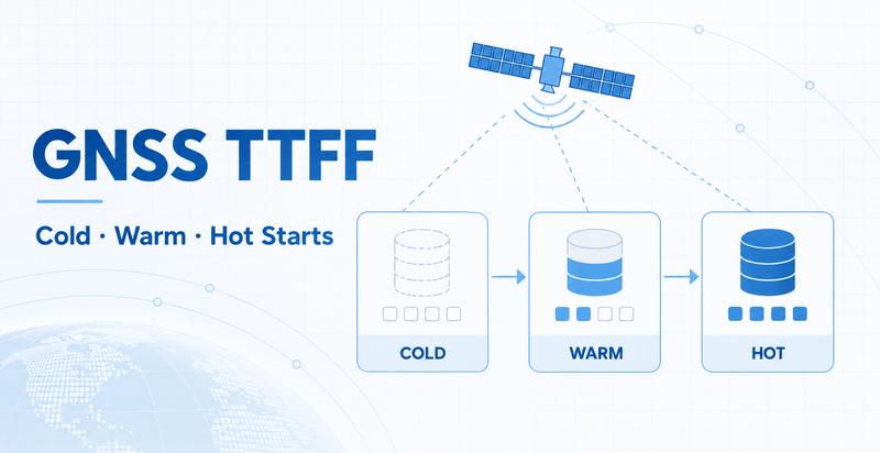
2. Testing cold, warm and hot start behavior when applicable
3. Recording satellite visibility and signal quality
4. Testing in open-sky and representative obstructed environments
5. Testing every intended product orientation
6. Enabling Wi-Fi, Bluetooth, cellular, displays and motors during GNSS operation
7. Comparing multiple prototype units
8. Testing the intended antenna, cable and connector combination
9. Repeating tests after enclosure or PCB changes
10. Confirming performance against the project’s acceptance criteria
Avoid evaluating a design from a single position fix. Stability, repeatability and behavior under realistic operating conditions are more useful than one successful laboratory result.
Before approving a GNSS design, confirm the following information.
- Target market and operating region
- Vehicle, handheld, stationary or industrial use
- Open-sky or obstructed environment
- Expected installation orientation
- Required update rate and positioning performance
- Supported satellite constellations
- Supported frequency bands
- Supply voltage
- Logic voltage
- Host interface
- Data format
- Configuration method
- Power modes
- Operating-temperature requirement
- Integrated, passive, active or external antenna
- Frequency-band compatibility
- Ground-plane requirement
- Keep-out requirement
- Antenna orientation
- Cable length and connector
- Active-antenna power requirement
- RF trace and stack-up
- Ground continuity
- Distance from noise sources
- Distance from other antennas
- Enclosure material
- Battery and display position
- Final mounting method
- Prototype quantity
- Test procedure
- Acceptance criteria
- Technical documents
- Firmware configuration
- Sample lead time
- Mass-production requirements
Providing this information early helps the module supplier recommend a more suitable integration approach and reduces redesign risk.
WEILA provides GNSS and BeiDou module options in several integration formats, including receiver modules, modules with integrated antennas and enclosed external receivers.
The appropriate solution depends on the confirmed application, antenna arrangement, signal environment, host interface, available space, power requirements and validation plan.
Engineers and procurement teams can share their project requirements with WEILA for module selection, integration discussion or customized PCBA evaluation.
It should be placed where it has the clearest practical view of the sky in the product’s normal operating orientation. Keep it away from metal structures, large batteries, displays, switching circuits and other antennas where possible.
It can simplify the design, but placement, ground plane, keep-out area, enclosure and interference still need to be evaluated. The complete device must be tested after assembly.
The antennas should be separated according to the complete RF design. There is no single safe distance for every product. Transmit power, frequency, antenna type, enclosure and operating modes must all be considered.
A passive antenna may suit compact designs with a short RF path and suitable antenna placement. An active antenna may be useful when the antenna is connected through a longer cable or requires additional gain. Compatibility, bias voltage, current and filtering must be confirmed.
The enclosure may change antenna tuning, block signals or introduce reflections. Batteries, displays, cables, metal parts and conductive coatings can also affect performance. Testing should be repeated in the final enclosure and mounting position.
Provide the application, target market, satellite systems, frequency bands, antenna type, interface, voltage, dimensions, operating environment, expected performance, sample quantity and production forecast.
Company Address
Floor 11, Block A, Building 9, Baoneng Science and Technology Park, Qingxiang Road, Longhua District, Shenzhen
Tel: +86 755-8329018
Business Hours
Monday–Friday
9:00 AM–6:00 PM (GMT+8)



+8613247518427



0755-8329018

13602688458

 Previous
 List
List