

 34
34
 1
1
Selecting a GNSS module is not simply a matter of comparing an accuracy figure, counting supported satellites, or choosing the module with the most frequency bands.
A device that performs well on an evaluation board may behave differently after the antenna, enclosure, power supply, host processor, and other wireless components are added to the final product.
The right selection process therefore starts with the complete system requirements—not with a part number.
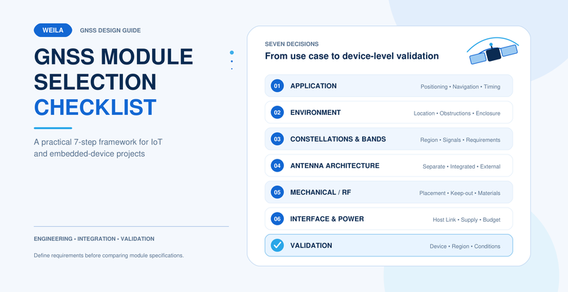
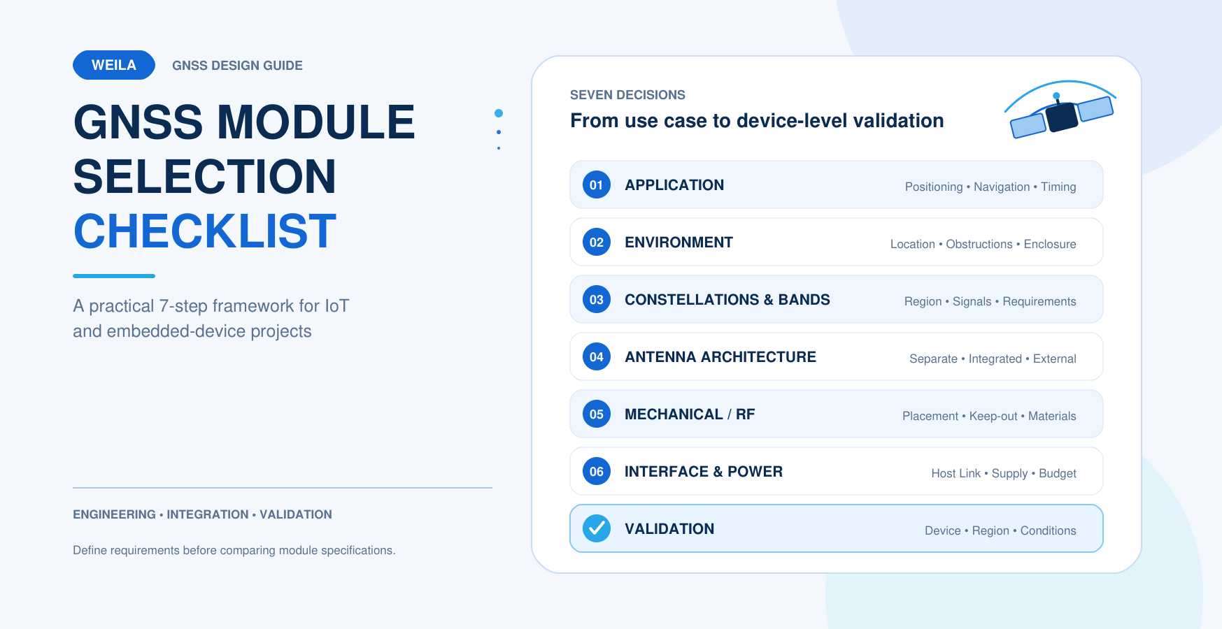
This checklist covers seven questions that engineers and technical buyers should answer before selecting a GNSS module for an IoT or embedded device.
Begin by defining the purpose of GNSS in the finished product. Positioning, navigation, tracking, and timing may use the same satellite signals, but they do not always place the same requirements on the receiver.
Positioning
A positioning device may only need to report its location at defined intervals. Examples include asset-location terminals, portable equipment, and connected IoT devices.
Important questions include how frequently a position is required, how long the device can remain active, and what should happen when a valid position is temporarily unavailable.
Navigation or Tracking
A moving product may require continuous position updates, stable performance during motion, and reliable communication with the host controller.
The required update rate, movement conditions, route environment, and acceptable latency should be defined before selecting the module.
Timing
A timing application must be evaluated according to timing-specific requirements.
Confirm whether the project needs a timing output such as 1PPS, what level of timing accuracy is required, and how the system should behave during temporary signal loss.
Do not assume that every positioning module automatically meets a project’s timing requirements.
Selection question: Is GNSS being used for periodic positioning, continuous navigation, tracking, timing, or a combination of these functions?
GNSS performance depends heavily on the signal environment. Open-sky operation is very different from operation near tall buildings, under foliage, inside a vehicle, or close to sources of electrical interference.
Define the expected environment as clearly as possible:
Open outdoor areas
Urban streets with reflected or blocked signals
Vehicle cabins or equipment enclosures
Areas with partial sky visibility
Locations close to cellular, WiFi or Bluetooth transmitters
Locations close to high-speed digital circuits or switching power supplies
Stationary, low-speed or high-dynamic applications
Buildings, metal structures, coated glass, the product housing, antenna orientation, and nearby electronics can all affect received signal quality.
For this reason, a module should not be selected only according to a laboratory specification measured under conditions that may not represent the final product.
Selection question: What obstructions, reflections, interference sources, and movement conditions will the receiver face during real operation?
Satellite constellation and frequency band are two different selection dimensions.
A multi-constellation GNSS module can receive signals from more than one satellite navigation system, such as BDS, GPS, Galileo or GLONASS, depending on the module configuration.
A multi-band GNSS module receives signals on more than one frequency band.
A module can therefore be multi-constellation while remaining single-band. These two specifications should not be treated as the same feature.
Choose the required constellations according to the target market, application requirements, and confirmed module support. Supporting more constellations may increase satellite availability in certain environments, but the actual benefit should still be evaluated in the finished application.
Frequency-band selection should be based on:
Operating environment
Required positioning performance
Antenna system
Power budget
Cost target
Product dimensions
Integration complexity
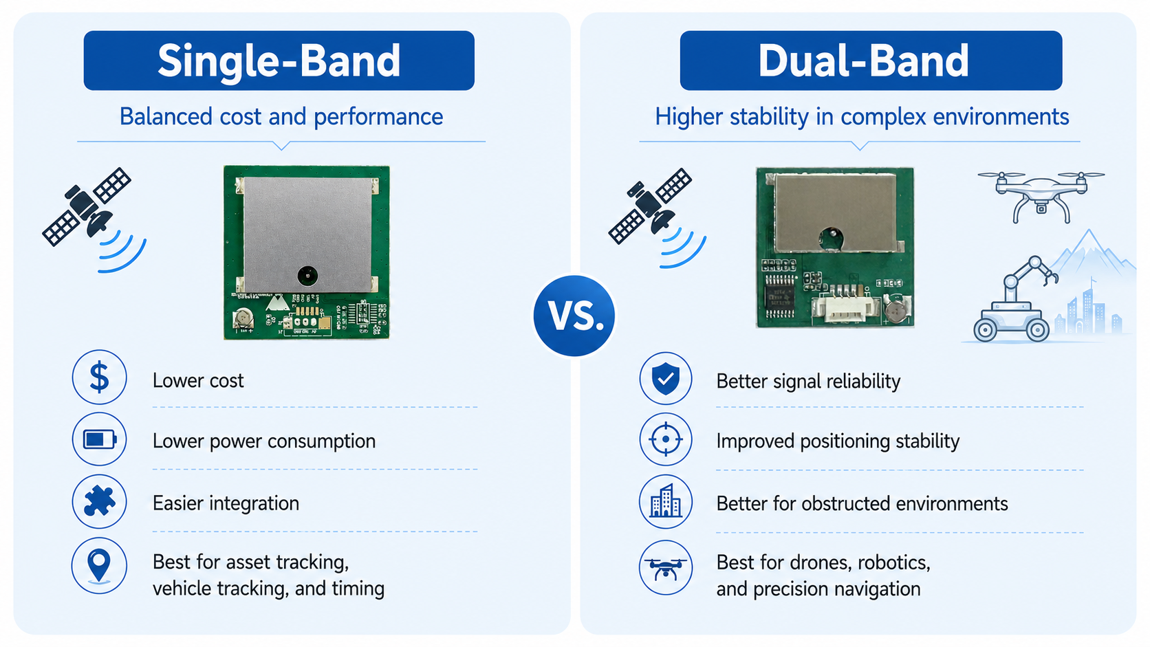
A dual-band solution is not automatically necessary for every project. A cost-sensitive device operating mainly in open-sky environments may have different requirements from equipment operating in urban areas with significant signal obstruction and reflection.
For a detailed explanation, read Single-Band vs. Dual-Band GNSS Modules: How to Choose the Right Solution.
Selection question: Which constellations and bands are genuinely required, and which are simply additional specifications without a clear project benefit?
The next decision is not only which GNSS receiver to use, but also how the receiver and antenna will be integrated into the product.
There are three common options.
Receiver Module With a Separate Antenna
This approach gives engineers more flexibility when choosing the antenna and installation position.
It may be suitable when the GNSS receiver and the best antenna location are in different parts of the device. However, the RF trace, connector, cable, antenna power supply, impedance matching, grounding, and PCB layout must all be considered.
This option generally requires more RF integration work.
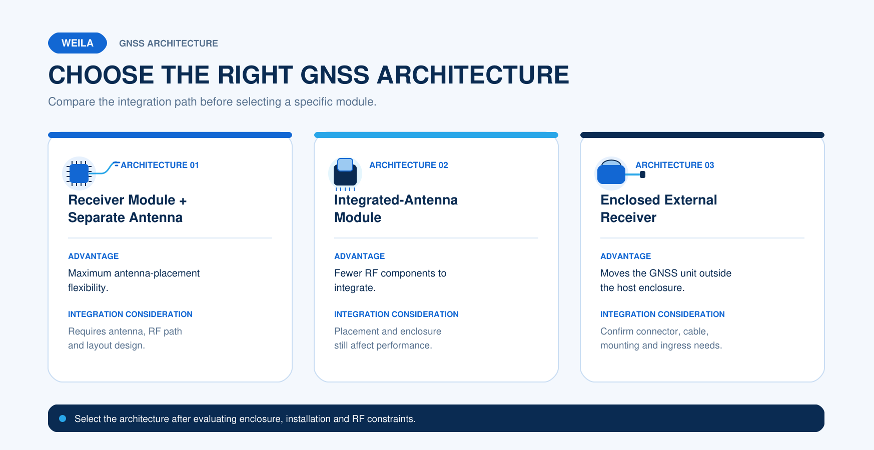
Module With an Integrated Antenna
An integrated-antenna module combines the GNSS receiver and antenna in one unit. It can simplify purchasing and assembly and may be suitable for compact devices.
However, integration is only simplified when the module can be installed in a suitable position. The final enclosure, antenna orientation, ground plane, and nearby components can still affect performance.
An integrated antenna does not remove the need for testing in the finished device.
Enclosed External GNSS Receiver
An enclosed external receiver allows the antenna to be installed away from noisy electronics or outside an enclosure with poor sky visibility.
Depending on the selected product, the host connection may use UART, USB, RS232, or another interface.
Engineers should confirm:
Cable length and routing
Connector type
Installation method
Host interface
Environmental exposure
Power supply
Enclosure requirements
Selection question: Does the product need maximum integration flexibility, simplified assembly, or an antenna that can be installed away from the main PCB?
The antenna is part of the complete GNSS system. It should not be treated as an accessory that can be selected after the PCB and enclosure have already been completed.
Before selecting the module, confirm:
Available PCB space
Available enclosure space
Antenna dimensions
Antenna orientation
Ground-plane requirements
Required keep-out area
Distance from metal, batteries, displays and cables
Distance from cellular, WiFi and Bluetooth antennas
Distance from switching power circuits
Active or passive antenna requirements
RF connector and cable-loss limits
Housing material
Final installation position
Patch antennas are widely used in GNSS products, but their performance depends on placement, orientation, and the surrounding ground plane.
Reducing antenna size or placing the antenna in a compromised location can affect the complete system, even when the selected receiver module has suitable specifications.
The antenna design should therefore be evaluated early. The complete device should then be tested in its real enclosure and intended installation orientation.
Selection question: Can the mechanical design provide the antenna with a suitable location, orientation, ground plane, and separation from interference sources?
The GNSS module must connect correctly to the host system. Engineers should check the complete electrical interface instead of looking only for the word "serial" or "UART".
Important items include:
Supply-voltage range
Logic-voltage level
UART, USB, RS232, or another host interface
Baud rate
Configuration method
Required NMEA messages
Position update rate
Timing output, if required
Backup supply or data-retention requirements
Active-antenna power supply, if applicable
Power-on and reset behavior
Standby and recovery behavior
Host MCU processing requirements
TTL-level UART and RS232 are not electrically interchangeable.
A product described as a serial GNSS receiver may still require a level-conversion circuit or a different connector before it can communicate with the host device. The exact interface and pin definitions must always be verified in the selected product documentation.
Power consumption should also be evaluated at the system level.
Average operating current alone does not describe startup behavior, acquisition time, backup operation, sleep modes, or the additional power required by an active antenna.
For battery-powered products, engineers should evaluate the complete operating cycle rather than relying on a single current figure.
Selection question: Are the module's voltage, signal levels, data output, update rate, power modes, and connector format compatible with the host design?
A datasheet can help narrow the candidate list, but sample testing should confirm the final selection.
The validation plan should use the intended:
Antenna
PCB
Enclosure
Power supply
Host processor
Cable
Connector
Installation position
Testing should represent the real use case and may include:
Cold, warm, and hot-start behavior under defined conditions
Time required to obtain a valid position
Position recovery after temporary signal loss
Stationary and moving operation
Open-sky and representative obstructed environments
Antenna orientation and enclosure effects
Coexistence with cellular, WiFi and Bluetooth communication
Coexistence with displays, motors and power converters
Power consumption across the complete operating cycle
Data-interface stability
Host compatibility
Performance in the target market or operating region
Required operating-temperature or environmental checks
Technical buyers should also confirm the documents and commercial support required by the project.
These may include:
Product datasheet
Hardware integration information
Protocol documentation
Sample availability
Customization scope
Production lead time
Product lifecycle expectations
Technical support process
Any required certification or compliance document should be verified for the exact model and configuration rather than assumed from an entire product family.
Selection question: What test conditions and supplier documents are required before the design can be approved for mass production?
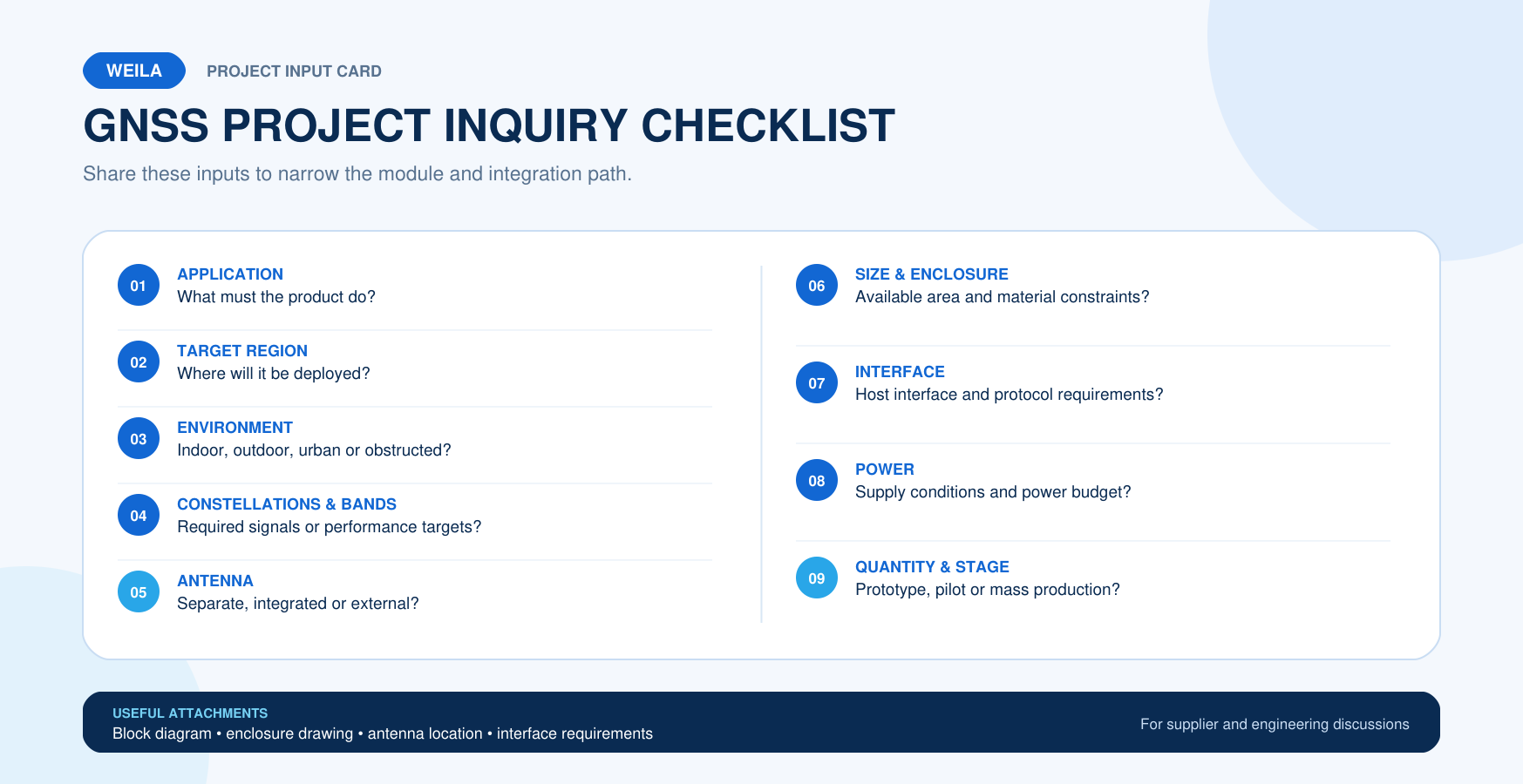
WEILA provides GNSS and BeiDou product options in several integration formats, including receiver modules, modules with integrated antennas, and enclosed external receivers.
The appropriate choice depends on the confirmed application, signal environment, antenna arrangement, host interface, mechanical space, power requirements, and validation plan.
Explore the WEILA GNSS and BeiDou module portfolio or share the checklist above with the WEILA team.
Providing complete project requirements at the beginning helps the engineering and sales teams recommend a more suitable module or discuss a customized PCBA solution when required.
Company Address
Floor 11, Block A, Building 9, Baoneng Science and Technology Park, Qingxiang Road, Longhua District, Shenzhen
Tel: +86 755-8329018
Business Hours
Monday–Friday
9:00 AM–6:00 PM (GMT+8)



+8613247518427



0755-8329018

13602688458

 Previous
 List
List