

 126
 0
Selecting a GNSS receiver is not only a question of constellations, frequency bands, sensitivity or positioning accuracy.
The antenna and its final installation can determine whether the complete product receives usable satellite signals in its intended operating environment.
An antenna that performs well on an open development board may behave differently after it is placed inside an enclosure, near a battery, display, metal bracket, motor or switching power circuit. For this reason, engineers should select the receiver and antenna architecture together.
Two common options are:
- A GNSS module with a built-in ceramic antenna
- A GNSS module or receiver connected to an external antenna
Neither option is automatically better. The right choice depends on the enclosure, installation position, available PCB area, cable routing, target environment and product-validation plan.
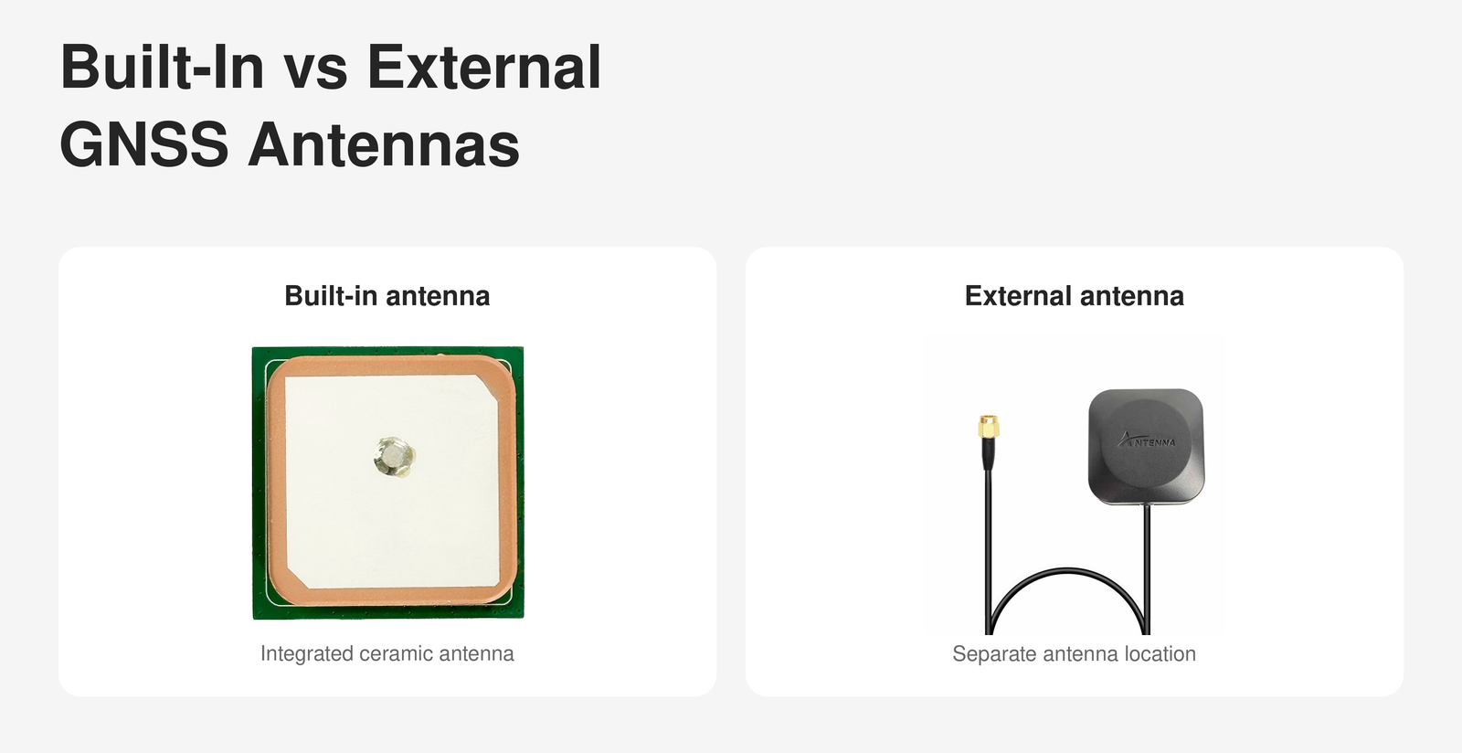
A built-in antenna is integrated directly into the GNSS module or host assembly.
A common implementation uses a ceramic patch antenna mounted above the receiver PCB. This creates a compact positioning assembly that can be installed without routing a separate RF cable to another part of the product.
Built-in antenna modules may simplify:
- Mechanical assembly
- Cable management
- Connector selection
- Purchasing
- Production handling
- Initial prototyping
They can be suitable for products that have:
- A non-metallic enclosure
- A defined upward-facing installation
- Sufficient clearance around the antenna
- Reasonable sky visibility
- Limited internal interference
- Enough space for the module and antenna structure
However, a built-in antenna must operate from the position available inside the finished product. If that position is deeply enclosed, surrounded by metal or close to noisy electronics, the convenient module format alone will not solve the RF problem.
An external antenna is installed away from the GNSS receiver and connected through an RF cable and suitable connector.
The antenna may be mounted:
- On top of an enclosure
- Near a window
- On a vehicle roof
- Above a metal cabinet
- At another location with better sky visibility
This separation gives the mechanical team more flexibility when the receiver PCB cannot be placed in a suitable RF location.
An external antenna architecture may be useful when:
- The main electronics are installed inside a metal enclosure
- The receiver is located under a dashboard or equipment panel
- The antenna must be positioned away from motors or power electronics
- The product requires a sealed external installation
- The antenna position and receiver position must be designed separately
- The installation needs a longer cable
An external antenna also introduces additional design decisions, including cable type, cable length, connector, antenna gain, supply requirements and mechanical protection.
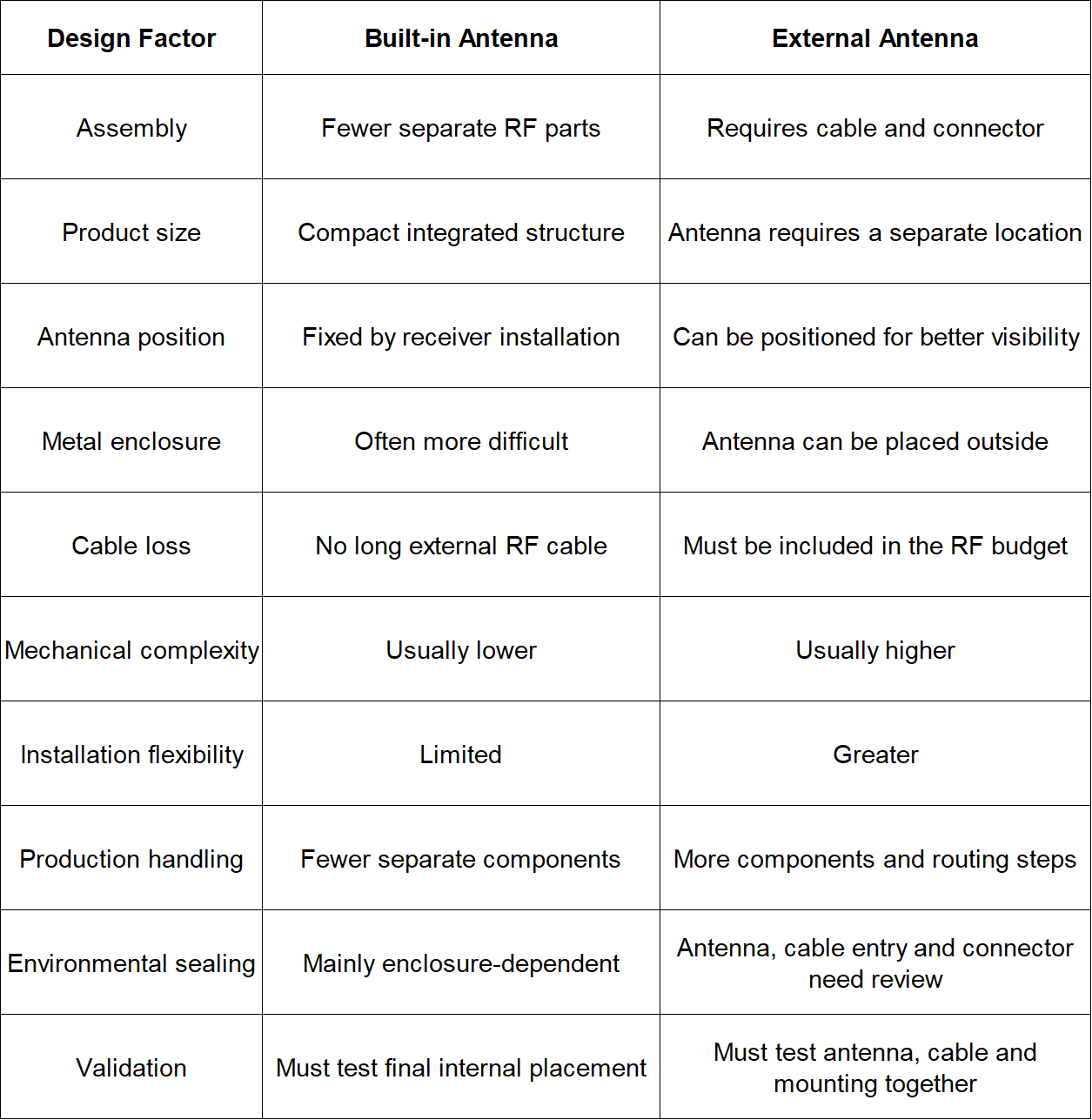
This comparison should be used as an architecture guide rather than a performance guarantee. Actual GNSS performance depends on the selected antenna, receiver, frequency bands, installation and operating environment.
The enclosure is one of the first items to review.
A plastic enclosure may allow the antenna to receive satellite signals, but its material, thickness, coating and internal structure can still affect performance.
Metal presents a greater challenge because it can block or strongly alter GNSS signals. A built-in antenna should not be assumed to work normally when it is placed inside a metal housing.
Review:
- Enclosure material
- Wall thickness
- Metallic paint or coating
- Internal metal brackets
- Battery location
- Display location
- Product orientation
- Expected mounting surface
- Distance between the antenna and enclosure
- Space above and around the antenna
The installation should also be evaluated in every normal product orientation. A receiver that is tested facing upward may perform differently when the finished product is mounted vertically or underneath another structure.
A ceramic patch antenna does not operate independently from its surrounding structure. Its performance can be affected by the PCB, ground area, nearby components and mechanical installation.
The exact layout requirements depend on the antenna and module design, so the current product manual and recommended layout should be reviewed before the PCB is released.
Important questions include:
Does the selected module require a specific ground area?
Is there sufficient clearance around the antenna?
Are high-speed digital traces routed nearby?
Is a switching regulator located close to the GNSS section?
Are displays, processors or memory devices potential noise sources?
Will the module be mounted near a battery or metal support?
Is the antenna orientation fixed during normal operation?
Do not copy an antenna layout from a different module without checking whether its mechanical and RF requirements are equivalent.
GNSS receivers process weak satellite signals. Noise generated inside the product can therefore reduce acquisition or tracking performance even when the receiver specification appears suitable.
Potential interference sources include:
- Switching power supplies
- High-speed processors
- Displays and display cables
- USB circuits
- Cellular transmitters
- Wi-Fi and Bluetooth radios
- Motors
- DC/DC converters
- Long digital traces
- Poor grounding
- Unshielded cables
The engineering team should compare GNSS performance with major subsystems enabled and disabled.
For example, testing only the GNSS module while the display, wireless radios and motor are switched off may hide a problem that will appear in normal use.
Moving the antenna away from the receiver can improve installation flexibility, but the cable and connector become part of the receiving system.
Review:
- Antenna frequency-band coverage
- Passive or active antenna type
- Cable type
- Cable length
- Connector type
- Cable loss
- Connector loss
- Required antenna supply
- Receiver antenna-bias capability
- Short-circuit protection
- Waterproofing and strain relief
- Mounting surface
- Target operating temperature
Longer cable is not automatically better. Additional cable length increases routing flexibility but may also increase signal loss.
An active antenna may include amplification to help compensate for cable loss, but it must be electrically compatible with the receiver. The required supply voltage, current and protection functions should be confirmed from the current module and antenna documentation.
A built-in antenna can support a compact design when the product has a suitable non-metallic enclosure and predictable operating orientation.
The design should still be tested when held by a user, placed near the body, carried in a bag or installed next to other electronics.
If the receiver electronics are installed under a dashboard or inside a metal structure, a remotely positioned antenna may provide more installation flexibility.
Confirm the installation location, cable length, connector, vehicle glass or body structure and nearby electronic equipment.
For a small asset tracker, the antenna decision should be made together with the battery, enclosure and mounting method.
A tracker mounted directly on metal may behave differently from the same device tested on a wooden bench. Test it on the actual target asset or a representative structure.
Industrial cabinets, motors and power converters may create both shielding and interference challenges. An external antenna can separate the antenna from the main electronics, but cable routing and environmental protection must be considered.
These applications require testing under actual movement, vibration, operating orientation and electronic load.
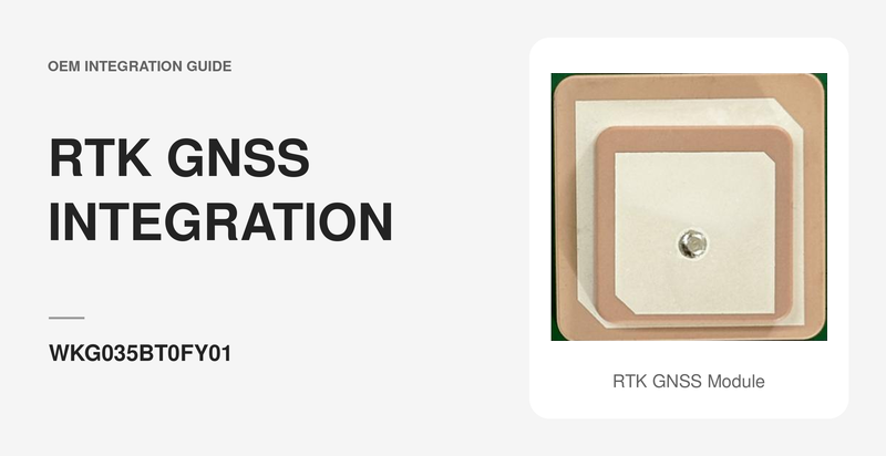
If the design uses dual-frequency or RTK positioning, the antenna must support the required signals. Centimeter-level positioning also requires compatible correction data and complete-system validation; it is not produced by antenna choice alone.
Receiver sensitivity is important, but it does not fully describe the finished product.
Two devices using the same receiver can produce different results because of:
- Antenna design
- Antenna placement
- Ground structure
- Cable loss
- Enclosure
- Interference
- Satellite visibility
- Firmware settings
- Operating orientation
Datasheet specifications should therefore be treated as module-level references. Approval should be based on tests using the actual antenna architecture and production-representative hardware.
A practical evaluation can be divided into six stages.
Test the receiver and proposed antenna in an open area with good sky visibility.
Record:
- Startup condition
- Time to the required position state
- Visible and used satellites
- Position output
- Antenna configuration
- Receiver configuration
Install the receiver on the proposed host board and repeat the test.
Compare the result with the baseline to identify layout, power or interference effects.
Test the assembly inside the intended enclosure.
Do not leave the cover open unless the finished product will normally operate that way.
Repeat the test with major systems enabled:
- Wi-Fi
- Bluetooth
- Cellular communication
- Display
- Motor
- Storage
- Charging
- Other normal loads
Install the product in its real or representative location.
For example:
- On the intended vehicle surface
- Inside the target cabinet
- On the actual tracked asset
- In the normal handheld orientation
- On the final robot or UAV structure
Repeat validation using the intended antenna, cable, connector, enclosure and PCB revision.
A development-board result should not be used as the only basis for approving production hardware.
To evaluate a built-in or external antenna solution, provide:
- Product application
- Required satellite systems and frequency bands
- Accuracy requirement
- Update-rate requirement
- Product dimensions
- Enclosure material
- Installation orientation
- Available antenna area
- Whether the product is mounted on metal
- Host interface
- Supply voltage
- Nearby radios and interference sources
- Preferred built-in or external antenna format
- Required cable length and connector
- Environmental requirements
- Expected sample and production quantities
This information helps the supplier evaluate the GNSS receiver, antenna structure and mechanical format as one system.
A built-in GNSS antenna can simplify assembly and support a compact product when the receiver can be installed in a suitable RF location.
An external antenna offers greater placement flexibility when the electronics are enclosed, shielded or located far from a position with good sky visibility. It also adds cable, connector, power and mechanical requirements.
The right decision should be based on the complete product—not the antenna type alone.
Before final module selection, review the enclosure, PCB, ground arrangement, interference sources, cable path and installation environment. Then validate the production-representative device under its real operating conditions.
WEILA provides GNSS and BeiDou module options with different antenna structures, interfaces and form factors. Share your application, antenna arrangement, enclosure and positioning requirements for a project-based evaluation.
No. Positioning performance depends on the receiver, antenna, cable, placement, satellite visibility, interference and operating environment. An external antenna may allow a better installation position, but it must still be selected and integrated correctly.
It may, provided the enclosure, surrounding components and installation offer a suitable RF environment. The finished enclosure must be tested because plastic type, thickness, coatings and internal structures can affect performance.
A metal enclosure can block or significantly alter satellite signals. An externally positioned antenna is often considered for this architecture, but the complete installation still requires validation.
Not by itself. A longer cable provides installation flexibility but also introduces additional signal loss. Cable type, length, connector loss and antenna gain must be reviewed together.
A passive antenna does not include amplification. An active antenna normally includes an amplifier and requires a compatible power supply from the receiver or system. Electrical compatibility must be confirmed before connection.
No. Sensitivity is one receiver characteristic. Finished-device performance also depends on antenna efficiency, placement, interference, enclosure, ground structure and test conditions.
Initial antenna evaluation should begin before the enclosure and PCB design are frozen. Final approval should use production-representative hardware in the intended installation environment.
Company Address
Floor 11, Block A, Building 9, Baoneng Science and Technology Park, Qingxiang Road, Longhua District, Shenzhen
Tel: +86 755-8329018
Business Hours
Monday–Friday
9:00 AM–6:00 PM (GMT+8)



+8613247518427



0755-8329018

13602688458

 Previous
 List